How to Choose an Electric Gripper for High-Mix Low-Volume Manufacturing: The Technical Variables That Actually Matter


On This Page
- 1. Stroke Range: Map It to Your Part Size Distribution, Not Your Largest Part
- a. Read the Number Right First
- b. Coverage Matters More Than Maximum Size
- c. The Cost of Under- and Over-Specifying Stroke
- d. Practical Selection Approach
- 2. Force Range: Apply a Safety Factor, Not the Nameplate Rating
- a. Why Static Part Weight Is Not Enough
- b. Recommended Force Margin
- 3. Jaw Motion Type: The Technical Variable Most Selection Guides Skip
- 4. Gripper Weight: The Payload Cost That Affects More Than Just Payload
- The practical implication
- 5. Control Interface: How Long Before It Actually Works
- 6. Encoder Type: When Initialization Downtime Is a Real Cost
- a. Incremental vs. Absolute Encoders
- b. Where the Difference Matters
- c. Power Loss: Hold or Release?
- 7. IP Rating: Match It to the Actual Environment, Not the Worst-Case Scenario
- 8. Applying the Framework: SusGrip 2F and 3F
- a. One gripper for different parts
- b. Built for demanding production environments
- c. Deployment without initialization overhead
- d. Weight and footprint
- e. Choosing between them
- f. Compatibility with various robots
- Conclusion
Key Takeaway
- Choose stroke for part-mix coverage, not maximum part size. Aim to cover the parts you handle most often without changing tooling.
- Size grip force for real surface conditions. Friction, fingertip material, and acceleration can matter as much as part weight.
- Parallel jaws simplify changeovers. Once the robot path is programmed, it can be reused across different part sizes with pre-programmed jaw positions.
- Check the control interface, not just the hardware. Plugins and fieldbus connections may provide different levels of control and diagnostics.
- Consider weight, footprint, encoder type, and IP rating together. These factors affect payload, access, recovery, and reliability.
Most engineers evaluating grippers for high-mix low-volume manufacturing eventually arrive at the same conclusion: an electric gripper offers more flexibility than a pneumatic alternative. However, electric grippers differ significantly in stroke range, force capability, jaw motion, encoder architecture, environmental protection, and weight. Selecting the wrong combination can lead to unnecessary changeovers, downtime, and performance limitations in production.
This article examines six technical variables that help engineers identify an electric gripper for high-mix low-volume manufacturing environments.
1. Stroke Range: Map It to Your Part Size Distribution, Not Your Largest Part
a. Read the Number Right First
Different gripper manufacturers may define stroke differently. Some specify the total jaw opening, while others specify the travel of each finger. For the same gripper mechanism, this can result in specifications such as 64 mm or 128 mm.
Three-finger concentric grippers are different again. Instead of jaw opening, the more useful specification is the range of workpiece diameters the gripper can center.
So, don't compare stroke numbers directly across different grippers.
- Check how each manufacturer defines the measurement.
- Compare the actual range of part sizes the gripper can handle.
b. Coverage Matters More Than Maximum Size
When choosing a gripper stroke, it is tempting to size the gripper around the largest part in the production mix. This can work, but it may also lead to an unnecessarily large gripper. A better approach is to look at how much of your part mix a given stroke range can cover without a tooling change.

Illustrative part-size distribution for stroke coverage.
A shorter-stroke gripper may only cover smaller and mid-size parts, while a longer-stroke gripper, such as SusGrip 2F with its 128 mm stroke, can cover a wider share of a typical high-mix part family in a single setup. Whether the extra coverage justifies the added size, weight, or cost depends on how often the largest parts run and how long a tooling change takes.
-480x270.png)
Apicoo SusGrip 2F with long stroke in a compact body (128mm stroke in a 114mm body)
Coverage also depends on where the range sits, not just how wide it is. The gripper still has to close down to your smallest part and open far enough for your largest. Check both ends of the range, rather than looking at total stroke alone.
One case is worth checking separately: part families that need both internal and external gripping. Here, fingertip thickness no longer cancels out the way it does with single-direction gripping - it can add roughly four times its value to the required stroke. If your mix includes both grip types, thinner fingertips are worth real range.
c. The Cost of Under- and Over-Specifying Stroke
Under-specifying stroke can bring back the tooling-change problem you were trying to avoid. If an electric gripper requires a finger swap every time a part falls outside its stroke range, much of the flexibility advantage is lost.
Over-specifying stroke has a different cost. A larger gripper can add weight at the robot wrist without providing much benefit for most production runs. On smaller cobots operating close to their rated payload, that extra weight can reduce the effective payload. Depending on the robot, it can also limit achievable cycle speeds.
d. Practical Selection Approach
- Map your part mix: List part families and how frequently they are produced.
- Prioritize coverage: Choose a stroke range that covers the highest-frequency parts without a tooling change.
- Handle outliers separately: For parts that rarely fall within the main production mix, consider dedicated fingers or tooling rather than sizing the baseline stroke around them.
2. Force Range: Apply a Safety Factor, Not the Nameplate Rating
a. Why Static Part Weight Is Not Enough
A gripper's force rating tells you how much gripping force it can apply. It does not tell you how much force your application actually requires.
The required gripping force depends on more than the part's weight. Two factors are especially important:
- Friction coefficient: The friction between the fingertip material and the part surface determines how much normal force is needed to hold the part. Smooth, machined metal surfaces typically have lower friction than cast or textured surfaces. A 500 g part with a low-friction surface may therefore require more gripping force than a 1 kg part with a rough surface.
- Dynamic loading: Robot acceleration increases the effective load on the gripper. At 2G acceleration, for example, the part experiences roughly twice its gravitational load during that phase of the move. If the force margin is too small, acceleration can consume it entirely.
b. Recommended Force Margin
Friction can vary significantly with fingertip material and surface condition. A 2 kg part with a soft polyurethane pad on a dry surface might need only around 60 N per jaw. The same part with a bare steel fingertip on a coolant-wet, machined surface can require close to 200 N.
As a rule of thumb, smoother, wetter, and more bare-metal surfaces require more gripping force relative to part weight. Coolant can significantly reduce the friction available at the contact surface.
For the heaviest or wettest parts in your mix, size the gripper based on the actual fingertip material and surface condition, not part weight alone.
Most electric grippers for cobots are rated around 60-100 N, which can be sufficient for parts up to roughly 5 kg under favorable friction conditions, such as dry, textured, or rubber-padded contact. On smooth, wet, or bare-metal surfaces, the same part may require two to three times more force. Parts coming directly from a CNC machine therefore deserve closer attention before assuming a mid-range gripper is strong enough.
3. Jaw Motion Type: The Technical Variable Most Selection Guides Skip
Parallel jaw motion and angular jaw motion use fundamentally different finger paths. In high-mix applications, that difference can have a direct impact on robot programming and changeover time.
Parallel Jaw Motion | Angular Jaw Motion |
Both fingers move along a straight, linear path. | The fingers pivot around a fixed point. |
Gripping depth remains constant regardless of jaw opening. | Gripping depth changes as the jaws open and close. |
A robot approach position programmed for a 30 mm part can be used for a 90 mm part by changing the jaw-width target. No path recalculation is required. | A different part size can require the robot's approach position to be recalculated to account for the change in gripping depth. |
In a dedicated production cell running one or two part types, this difference may have little practical impact. In a high-mix low-volume cell where part sizes change frequently, however, repeated path adjustments add setup time and create more opportunities for error.
This is also why stroke and jaw motion need to be chosen together. A long stroke only reduces changeover effort if the jaw motion does not reintroduce it elsewhere.
- Angular jaws suit dedicated cells, narrow part-size ranges, and cost-driven applications where changeovers are rare.
- Parallel jaws justify their higher cost when frequent part-size changes make reprogramming a recurring task.
There is also a mechanical trade-off. Parallel mechanisms generally require more body width as stroke increases, while angular mechanisms can achieve long stroke in a more compact envelope at the cost of changing gripping depth. When comparing long-stroke parallel grippers, check stroke-to-body-width ratio as well as the overall envelope required to access machine doors, fixtures, and workpieces.
Apicoo’s SusGrip is designed to overcome this trade-off. Its patented mechanism combines a Scott-Russell linkage with a four-bar parallelogram to deliver a long parallel stroke in a compact body. The result is 128 mm of stroke in a 114 mm-wide body, with consistent gripping geometry across the stroke.
Angular gripper | Parallel gripper | SusGrip | |
Stroke range | Large | Limited | Large |
Body size | Compact | Bulky for stroke | Compact |
Contact point | Angular contact shift | Stable, flat contact | Stable, flat contact |
Pinch point | Pinch point at cross | No pinch point | No pinch point |
4. Gripper Weight: The Payload Cost That Affects More Than Just Payload
A gripper's weight affects cobot performance in two ways: payload capacity and dynamic performance.
- Payload Impact: A 10 kg-rated cobot with a 1.25 kg gripper does not simply have 8.75 kg of usable payload. Actual payload capacity depends on the load's position relative to the flange, so check the robot's payload chart rather than relying on simple subtraction. On larger cobots, this is rarely a binding constraint. On smaller cobots operating near their rated payload, it can be. With a dual-gripper machine-tending tool, both grippers count toward the tool mass, along with cameras, lighting, and cabling.
- Cycle-Time Impact: Robot speed and acceleration limits are determined by the total moment load on each joint, which includes the gripper weight at the end of the arm. A heavier gripper reduces the maximum speed and acceleration the robot can sustain without exceeding joint load limits. In cycle-time-sensitive applications, this is a real performance variable - not just a payload calculation.

Apicoo Robotics SusGrip-2F weighs under 1 kg
Footprint is separate from weight. The key question is whether the assembled tooling can clear the machine door, chuck, or fixture wall.
On a dual-gripper tool, gripper width can effectively double. A 20 mm difference between models can become 40 mm or more at the tool, which may determine whether the robot can reach the chuck at all.
Check the assembled envelope, not just the gripper's own dimensions, against the tightest access point.
The practical implication
Gripper weight matters most on small cobots with 5–10 kg rated payloads and in applications where cycle time is a performance target. On larger cobots running parts well within their rated payload, a 200-300g difference between gripper models is unlikely to have a meaningful performance impact.
Footprint is different: it can become a constraint whenever the gripper enters a confined space, regardless of robot size.
Also confirm that the gripper mounts directly to your robot's flange standard. An adapter adds stack height, weight, and lead time.
When evaluating gripper options, check three things:
- Effective payload with the gripper installed, using the robot manufacturer's payload chart.
- Target cycle time under the resulting joint load limits.
- Assembled envelope at the tightest access point.
Most cobot manufacturers provide tools or payload calculators for the first two.
5. Control Interface: How Long Before It Actually Works
Two grippers with identical stroke and force can still differ by days of commissioning - and that cost never shows up on a datasheet. In high-mix cells it matters even more, because every new part is a program change, not a one-time setup.
A plugin puts the gripper into the robot's own programming environment. On a Universal Robots controller, for example, installing a URCap adds "Grip" and "Release" as program nodes right next to MoveJ and Wait. The operator can set target width and force directly on the pendant.
Techman, Doosan, JAKA, and FANUC CRX each have their own equivalent. Without a plugin, the same commands typically go through a socket connection that must be scripted and parsed manually. This is workable, but it makes later changes more dependent on the person who wrote the integration. In a cell with weekly changeovers, that can mean the difference between a technician adjusting grip width on the pendant and calling the integrator.
SusGrip Series can be plug and play on a wide variety of robot arms
One thing worth checking: the plugin and the gripper's underlying fieldbus often don't expose the same capability. A plugin might offer grip, release, and a simple "part detected" flag, while the fieldbus underneath carries continuous jaw position, adjustable force, and diagnostic data that never reaches your program through the plugin.
Ask the vendor directly what's available over fieldbus that the plugin can't reach, and whether the plugin is actively maintained for your controller's firmware version.
6. Encoder Type: When Initialization Downtime Is a Real Cost
a. Incremental vs. Absolute Encoders
Electric cobot grippers typically use either incremental or absolute encoders to track jaw position.

- Incremental encoder: Tracks motor rotation relative to a reference point. If the gripper loses power through an E-stop, power cut, or restart, it loses that reference. The gripper must then run a homing sequence before accepting position commands again.
- Absolute encoder: Reports the actual jaw position regardless of power state. No homing sequence is required, so the gripper can resume operation immediately after power is restored, from the position it was in when power was lost.
The difference goes beyond restart time. An incremental encoder's position is relative to its last homing point, so its reading cannot be compared reliably with a position stored before the power cycle. That is sufficient for basic jaw positioning, but not for applications that need persistent position data, such as detecting a wrong part or tracking fingertip wear over time.
An absolute encoder maintains a position reference across power cycles, making this information available without reinitialization.

Recovery timeline: incremental vs. absolute encoder after power loss.
b. Where the Difference Matters
The operational difference is most visible in two scenarios.
- Lights-out or overnight operation: if the cell stops unexpectedly, an absolute encoder allows a faster restart without manual intervention to run a homing sequence.
- E-stop recovery during normal production: on a busy line, e-stops triggered by safety systems are a routine occurrence.
For applications where uptime and restart speed matter, encoder type is worth specifying explicitly rather than treating it as a secondary feature.
c. Power Loss: Hold or Release?
Encoder type isn't the only consideration when power drops. You should also ask whether the gripper holds or releases the part.
Some grippers are mechanically self-locking and maintain their grip without power. Others lose grip force when power is cut. This is a safety and risk-assessment question, not just a convenience feature. It determines what happens to a part held above a machine bed or near an operator if the cell stops unexpectedly.
7. IP Rating: Match It to the Actual Environment, Not the Worst-Case Scenario
Electric grippers contain motors, encoders, and circuit boards - components that are sensitive to moisture, coolant mist, and airborne particles. Machine tending environments generate all three. Insufficient environmental protection often leads to gradual failures that are difficult to diagnose, including:
- Intermittent encoder faults
- Motor performance degradation
- Long-term corrosion of electronic components
The required IP rating depends on the actual operating environment.

IP ratings are standardized: the first digit indicates protection against solid particles, the second against liquids.
IP Rating | Solid Protection | Liquid Protection | Typical Environment |
IP54 | Dust-protected | Splash from any direction | Light industrial, limited fluid exposure |
IP65 Recommended | Dust-tight | Low-pressure water jets | Most CNC tending applications with coolant mist |
IP67 | Dust-tight | Immersion up to 1m | Direct coolant exposure or wash-down environments |
Unlike stroke, force, or jaw motion, environmental protection can sometimes be supplemented after purchase. Covers and shrouds can keep chips off the body, while sealed cable glands and protected connector terminations can reduce exposure at cable entry points.
These measures work well against chips, swarf, and incidental splash. Cable entries are often the weakest point on an otherwise well-protected gripper and are worth addressing first. They're far less effective against coolant mist, which reaches everywhere, or pressurized coolant, which finds any unsealed path. Moving components such as jaw guides and rails are also harder to protect because sealing a moving surface can introduce wear or restrict travel.
One caveat: a field-modified gripper no longer carries its original rated IP, which can matter for compliance or warranty - worth confirming with your vendor before relying on added covers for a formal risk assessment.
8. Applying the Framework: SusGrip 2F and 3F
SusGrip isApicoo Robotics' electric gripper' electric gripper series, built for high-mix cobot applications.
Variable | SusGrip 2F | SusGrip 3F |
Stroke range | 128mm | 10–150mm |
Gripping force | 140N | 140N |
Jaw motion type | Parallel | Parallel, Concentric |
Gripping direction | External and internal | External and internal |
Encoder type | Absolute | Absolute |
Hold on power loss | Mechanical self-lock | Mechanical self-lock |
Environmental protection | IP54 standard, IP67 optional | IP54 standard, IP67 optional |
Weight | 990g | 1540g |
a. One gripper for different parts
128mm on the SusGrip-2F and up to 150mm on the SusGrip-3F put both models well above the 85mm ceiling of most standard parallel grippers. In practice, this means a single gripper configuration handles the majority of a high-mix line's part range without tool changes. Both models also support commanded gripping in either direction - external or internal - so the same setup can hold a turned part on its bore in one operation and on its outside diameter in another.
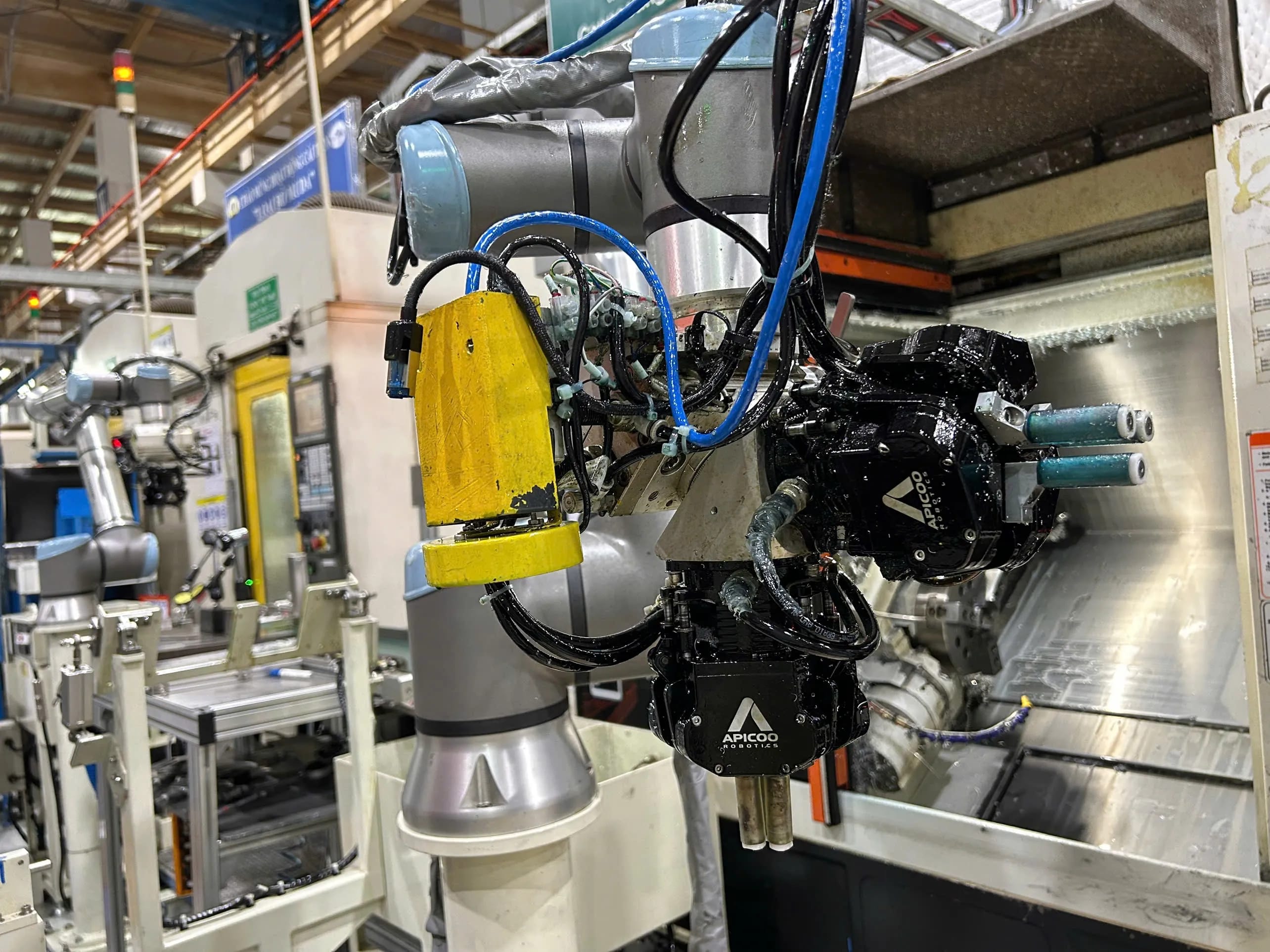
In fact, the SusGrip-3F has been deployed on cells running 43 SKUs across a 25–157mm diameter range, switching between parts entirely through software, no engineer interruption needed.
See how gripper choice affects the broader machine tending setup.
b. Built for demanding production environments
SusGrip was designed for environments where oil contamination, metal chips, and heavy workpieces are routine, not edge cases - IP54 as standard covers chips, dust, and incidental splash for most assembly and dry machine tending, with an IP67 option available for cells with direct coolant exposure or wash-down.
c. Deployment without initialization overhead
Both models use absolute encoders, so there is no homing sequence after power-on, an e-stop, or an unplanned restart - the gripper is ready to run immediately, at whatever jaw position it was in when power was lost. That same absolute reference also keeps jaw-position readings valid across power cycles, which is what makes wrong-part detection reliable rather than approximate.
Both models are also mechanically self-locking, holding the part when power is removed - a useful answer to have ready for a cell's risk assessment.
d. Weight and footprint
At 990g the SusGrip-2F is light for its force class. On a dual-gripper tool, that difference is doubled - worth checking against your width and payload budgets rather than treating as a rounding error.
e. Choosing between them
SusGrip-2F suits parts that are prismatic or flat, where weight matters and a wide parallel span covers the family. SusGrip-3F suits round or symmetric parts, where concentric centring removes a fixturing step - the gripper locates the part rather than merely holding it.
f. Compatibility with various robots
Combined with plug-and-play integration across UR, JAKA, Techman, Doosan, and FANUC CRX platforms,etc, this reduces both initial setup time and the operational friction that accumulates over a production week.
Conclusion
In high-mix, low-volume manufacturing, the value of an electric gripper comes from how much friction it removes from frequent product changes. The right stroke range can reduce tooling changes, parallel motion can simplify robot reprogramming, and an absolute encoder can shorten recovery after stops. Force, IP rating, and gripper weight then determine whether that flexibility remains reliable and practical on the production floor.
This is the direction of smart manufacturing: automation that can adapt quickly to changing production requirements, while reducing the need for manual setup and specialist intervention.
The goal is not to maximize every gripper specification. It is to choose a combination that keeps your HMLV cell flexible, fast to reconfigure, and easier to operate day after day.
For engineers evaluating SusGrip, contact us for full specifications and a 35-day free trial program.